Linear Actuators

000

Introduction

This includes everything you need to know about linear actuators.

You will learn:

  • What is a Linear Actuator?
  • Types of Linear Actuators
  • How Does a Linear Actuator Work?
  • Linear Actuator Design
  • And much more…


Linear actuator by Deltron Precision, Inc.

Chapter One – What is a Linear Actuator?

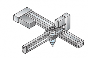
A linear actuator is a means for converting rotational motion into push or pull linear motion, which can be used for lifting, dropping, sliding, or tilting of machines or materials. They provide safe and clean motion control that is efficient and maintenance free. Electric linear actuators use a DC or AC motor with a series of gears and a lead screw that pushes the main rod shaft. The difference between actuators is determined by the size of the motor. Static and dynamic are the two load capacity variables of a linear actuator. Dynamic load capacity is the amount of force being applied when the actuator is in motion. Static load capacity is when the actuator is motionless and holding a load in place. This adhesive applicator in the diagram is using an actuator to repeatedly apply an adhesive, what used to be a manual operation.

Actuators open automatic doors, move car seats forwards and back, and open and close computer disk drives. The basic principle behind a linear actuator is the concept of an inclined plane, where the lead screw of the actuator continues along a ramp of small rotational force.

Adhesive Application Process using an Actuator

(from intelligentactuator.com)

Chapter Two – Types of Linear Actuators

Linear actuators come in several configurations to fit any possible application, environment, setting, or industry. They are categorized by their mechanical drive mechanism, guide, and housing. Below is a brief explanation of some of the common types.

Types of Linear Actuators

Mechanical Actuators

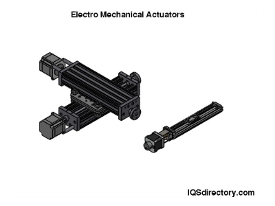
Mechanical Actuators is the simplest form of actuator that converts rotary motion into linear motion. Ball screw, leadscrew, rack and pinion, belt driven, and cam actuators are categorized as mechanical. Below are mechanical actuators from Venture Mfg. Co. in Dayton, Ohio.

Hydraulic Actuators

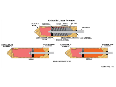
Hydraulic Actuators are hydraulic cylinders with a piston that use an incompressible liquid to produce unbalanced pressure on the piston to create linear displacement. In the pictured hydraulic actuator, the fluid, under pressure, enters through the port to the left of the chamber and pushes against the face of the piston. When the pressure on the fluid is released, the piston moves back to the left.

Pneumatic Actuators

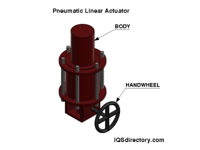
Pneumatic Actuators rapidly produce low to medium force and are used as servo devices. Pneumatic linear actuators use compressed air to convert energy into mechanical motion. They consist of a piston, cylinder, and valve or port, which can produce linear or rotary mechanical motion.

Piezoelectric Actuators

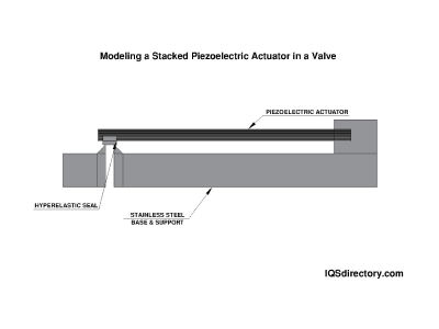
Piezoelectric Actuators use the piezoelectric effect, which is electricity created by pressure and latent heat resulting in an electromechanical interaction between mechanical and electrical states. Piezo actuators have multiple layers of piezo elements, such as ceramics, which combine the effect of each element’s expansion to create movement.

The diagram below is of a stacked piezoelectric actuator that is designed to open or close a valve.

Coiled Actuators

Coiled Actuators have magnets that generate a magnetic field, which produces current to move a coil to create motion in a shaft or shuttle. The force of the motion is proportional to the turns of the coil and the magnetic flux as well as the current. Increasing current increases the force.

Electro-Mechanical Actuators

Electro-Mechanical Actuators are programmable so the force and motion profile can be changed using a computer. Though electro-mechanical actuators are similar to mechanical actuators, they have the significant difference of using an electrical servo motor to generate rotary motion. Some of the different aspects of an electro-mechanical actuator are simplified, standard, and compact designs.

The YouTube video below, from Ultra Motion, provides an explanation of how to program an electro-mechanical actuator. The diagram below is of a stacked piezoelectric actuator that is designed to open or close a valve.

Telescoping Actuators

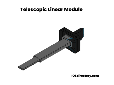
Telescoping Actuators are used where space is limited and come in several forms, which include rigid belt, segmented spindle, rigid chain, and helical band. A common form of telescoping linear actuator has tubes that are equal in length that extend and retract inside each other, much like a handheld telescopic. The range of motion of a telescoping actuator is greater than its unextended length.

Ball Slide

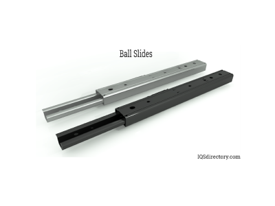
Ball-guided positioning linear slides have precision accuracy and stiffness. They have low friction and smooth, accurate motion for a wide range of loading configurations. Balls run on a pair of tracks without creating friction, wear, or skidding at preload. They are non-magnetic making them perfect for applications that need to avoid magnetic interference.

Leading Linear Actuator Manufacturers and Suppliers

Chapter Three – How Does a Linear Actuator Work?

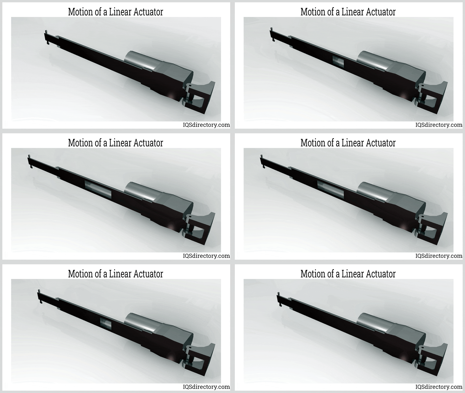
A linear actuator actuates, or moves, in a linear straight line. Though the basic function of an actuator is the same, there are different ways that motion is achieved. The uses of linear actuators include wheelchair ramps to toys and technological instruments for spacecraft. The operation of an actuator is fairly simple. A screw, known as a lead screw, creates motion by turning clockwise or counter clockwise, which causes a nut on the screw to move creating linear motion. The motion of the screw of a linear actuator can be seen in this diagram. The motor, above the actuator, supplies the energy to turn the screw.

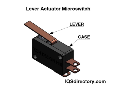
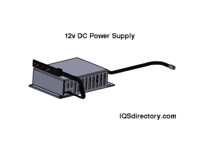
The power supply is from a DC or AC motor. The typical motor is a 12v DC, but other voltages are available. Actuators have a switch to reverse the polarity of the motor, which makes the actuator change its motion. The speed and force of an actuator depends on its gearbox. The amount of force depends on the actuator’s speed. Lower speeds supply greater force because motor speed and force are constant. One of the basic differences between actuators is their stroke, which is defined by the length of the screw and shaft. Speed depends on the gears that connect the motor to the screw. The mechanism to stop the stroke of an actuator is a limit or micro switch, which can be seen in the image below. Microswitches are located at the top and bottom of the shaft and are triggered by the up and down movement of the screw.

Components of a Linear Actuator:

Power source

This is the AC or DC motor that provides the energy necessary to drive the actuator. Though electricity is the most common source of energy, air and fluid energy is also used.

Power converter

The power converter supplies power from the source to the actuator using the measurements from the controller. Examples of industrial power converters are hydraulic proportional valves and electrical inverters.

Actuator

The Actuator is the actual device.

Mechanical load

The load driven by the actuator. The load capacity is determined by a mathematical formula or a load capacity chart. Loads are calculated for vertical and horizontal configurations as well as movement along the X and Y axes. An actuator has two forms of loads – static and dynamic. Static is when the actuator is stopped, while dynamic is when it is in motion. Each form of load has a capacity range.

Controller

The Controller ensures proper system function. It allows an operator to input quantities and setpoints.

Chapter Four – Linear Actuator Design

Linear actuators are designed for efficiency and ease of use. The basis of a linear actuators design is the inclined plane and begins with a threaded lead screw, which serves as a ramp to produce force that acts along a larger distance to move the load. The purpose of any linear actuator design is to provide push or pull motion. The energy to supply that motion can be manual or an energy source, such as air, electricity, or fluid.

Linear Actuator Design

Power

Power is the first consideration when designing a linear actuator. To get mechanical power out, it is necessary to have power in. The amount of mechanical power out is defined by the force or load to be moved. Manufacturers supply data regarding these factors on performance graphs and charts that include force (F), speed (V), and current draw (I), which determine what load the actuator will be able to move.

Duty Cycle

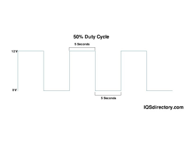
The duty cycle is how often the actuator will operate and the amount of time it will take. The temperature of the actuator while in motion determines the duty cycle since power is lost through heat. Following the duty cycle guidelines helps ensure that the actuator does not overheat the motor and damage the actuator’s components. Since not all actuators are the same, there is a variation in their duty cycles. Another factor is the load, which is especially true of DC motors. Other factors that can determine the duty cycle are ambient temperature, loading characteristics, and age.

Efficiency

Knowing the efficiency of an actuator helps to understand how it will perform when in operation. For a ball screw actuator, its efficiency will determine whether there is a need for holding brakes. The efficiency of an actuator is found by dividing mechanical power produced by electrical power. The resulting answer is its efficiency rating as a percentage.

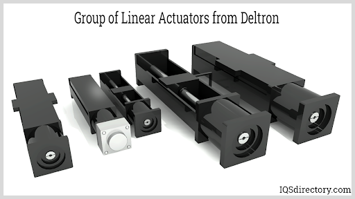
Group of Linear Actuators (from Deltron)

Actuator Life

There are various factors that affect the life of an actuator. As with any industrial tool, the care of an actuator can have a great deal to do with its longevity. Some of the factors that can extend the life of an actuator are:

Staying within the rated duty cycle – The duty cycle is a balance between usability and lifespan. The chart below, from Actuonix Motor Devices, provides an example of a typical duty cycle.

Minimize side load –Since actuators are designed to push and pull, side loading significantly reduces how they will be useful. The internal friction caused by side loading rapidly wears out its components. If a side load is necessary, using a slide rail with the actuator will extend its life span.

Staying within the recommended voltage – By applying more voltage than is recommended, the actuator will run faster for a short time but will wear out quicker.

Force – Actuator has a defined load capacity, such as 20 pounds. Operating it below its designed maximum capacity will extend its life.

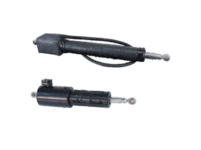
Extreme environments – Though most actuators are designed to operate in industrial environments, it is best to avoid extreme heat, cold, dirt or dust, and moisture. There are actuators that are designed to operate underwater and may be a choice for damp or moist conditions. The actuator below, from Ultramotion, is designed for underwater use.

Underwater Linear Actuator (from ultramotion.com)

Chapter Five – Load Capacity

Linear actuators can be used for tension, compression, or both to produce pushing or pulling forces. The two measurements for a linear actuator load capacity are dynamic and static. When a linear actuator is in the dynamic position, it is in motion or moving. In the static position, it is not moving and is holding a load in a set position. The load capacity of a linear actuator is determined by its ability to move and hold a load. Loading refers to the forces that push towards or compress the actuator as well as the forces that pull away from it. Dynamic load capacity is a test that determines the number of revolutions of linear motion that can be achieved by a linear actuator before fatigue, which is determined by the presence of flaking on rolling elements and the rated life of a rolling element. The International Organization of Standards (ISO) standard 14728-1:2017 describes the load fatigue for linear actuators. The dynamic, working, or lifting load capacity is the force that will be applied to the linear actuator when it is in motion and is what is needed for it to move something. It is the load the actuator will see when it is powered, extending or retracting, and how much it will push or pull. When a load is in static position, it is fixed or stationary and not moving. Static load capacity is determined by how much an actuator can safely hold without back driving or being damaged.

Chapter Six – Uses for Linear Actuators

Modern linear actuators look much the same as they did when they were first introduced. Technological advances have significantly improved the precision of their production and the source of their power. Engineering, materials, technology, and physics has seen the expansion of the use of linear actuators into a wide and diverse array of industries and applications. Though many of us do not notice them, we have contact with linear actuators at stores, the office, and schools. They have become the backbone of technological advancements and development.

Uses for Linear Actuators

Space exploration

In space exploration, every part of the vehicle has to be put to maximum use, while keeping weight down. Micro linear actuators save room and are useful for operating robotics and doing minor tasks. They are used to open and close valves, tracking, securing locking systems, and moving robotic arms.

Automobiles

One of the most common uses for linear actuators in cars is powered tailgates. Self opening and closing tailgates have become extremely popular and convenient. Linear actuators are also used for opening and closing side doors and activating air brakes.

Medicine

Linear actuators are a part of the most advanced medical equipment. A critical function for health care personnel is lifting patients, which is made easier with linear actuators on beds and chair recliners. Nurses can easily adjust the height of the bed for patient’s treatment. Monitoring equipment such as ventilators and temperature control devices have their height adjusted using linear actuators.

Snowblower

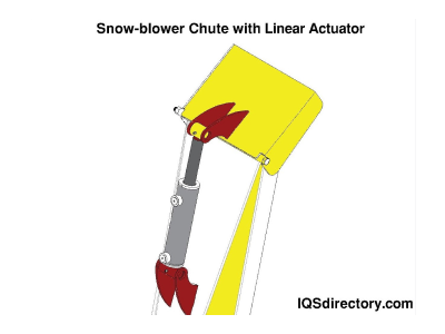
One of the problems of operating a snowblower is constantly changing the direction of the chute. Since operating a snowblower requires the use of both hands, reaching to change the position of the chute is difficult. A recent development in linear actuator technology is a switch that changes the position of the chute by pressing a thumb against an activation switch. The chute on the snowblower pictured below has a linear actuator on its side for easy repositioning.

Robotics

The automotive industry is using robotics to improve production quality and accuracy, while controlling the cost of production. Electric linear actuators control and repeat precise movements, control rates of acceleration and deceleration, and control the amount of required force. In bar feeders, actuators, with controllers, insert rods into the machine and adjust the optimum height. Rodless actuators are able to move pallets and position lumber for cutting and packaging.

Chapter Seven – How to Choose a Linear Actuator

Though there are multiple and varied types of linear actuators, when making the decision to purchase one, it is important to select the right actuator for the job. When purchasing an actuator, it is important to know the requirements that best suits your situation. Below are some considerations regarding how to choose the right actuator for the job.

Assessment:

When examining where the actuator will be placed, it is important to determine the type of motion that is required. Opening and closing a door or valve is different from activating a process on a machine. Actuators are designed to move objects in a straight line or produce circular motion. Assessing these motions and how they fit into your process is essential.

Automobiles

One of the most common uses for linear actuators in cars is powered tailgates. Self opening and closing tailgates have become extremely popular and convenient. Linear actuators are also used for opening and closing side doors and activating air brakes.

Medicine

Linear actuators are a part of the most advanced medical equipment. A critical function for health care personnel is lifting patients, which is made easier with linear actuators on beds and chair recliners. Nurses can easily adjust the height of the bed for patient’s treatment. Monitoring equipment such as ventilators and temperature control devices have their height adjusted using linear actuators.

Snowblower

One of the problems of operating a snowblower is constantly changing the direction of the chute. Since operating a snowblower requires the use of both hands, reaching to change the position of the chute is difficult. A recent development in linear actuator technology is a switch that changes the position of the chute by pressing a thumb against an activation switch. The chute on the snowblower pictured below has a linear actuator on its side for easy repositioning.

Robotics

The automotive industry is using robotics to improve production quality and accuracy, while controlling the cost of production. Electric linear actuators control and repeat precise movements, control rates of acceleration and deceleration, and control the amount of required force. In bar feeders, actuators, with controllers, insert rods into the machine and adjust the optimum height. Rodless actuators are able to move pallets and position lumber for cutting and packaging.
Conclusion

  • Linear actuators convert rotational motion into push or pull linear motion, which can be used for lifting, dropping, sliding, or tilting machines or materials.
  • Though the function of all linear actuators is the same, there are several different ways the motion is achieved.
  • The basis for a linear actuator’s design is an inclined plane.
  • Linear actuators come in several configurations to fit any possible application, environment, setting, or industry.
  • Modern linear actuators look much the same as they did when they were first introduced.
  • Static and dynamic are the two load capacity variables of a linear actuator.